
Online Feature: Highlights of API 685 3rd Edition, Sealless Pumps—Part 1
AUTHORS: F. Korkowski, Applied K3nowledge Consulting, Brea, California; T. Hess, E²G | The Equity Engineering Group, Inc., Philadelphia, Pennsylvania; J. Cooper, Bechtel Energy, Houston, Texas; and M. V. D. Heuvel, bp, Randstad, the Netherlands
The American Petroleum Institute (API) 685 3rd Ed. standard, “Sealless Centrifugal Pumps for Petroleum, Petrochemical and Gas Industry Process Service” has been updated to the third edition and published in July 2022. It addresses both magnetic drive pumps (MDPs) and canned motor pumps (CMPs).
Due to the nature of the extensive work done to compose the third edition, there are three parts to this article. Part 1 addresses the significant changes to the standard, Part 2 includes other changes of interest to the reader, and Part 3 focuses exclusively on secondary containment/secondary control, along with associated instrumentation requirements. The contents of this article were first published at the Turbomachinery and Pump Symposium held in Houston, Texas (U.S.) in September 2022.
This article—Part 1—describes the process of updating the document and cites the participating companies contributing to this work, along with addressing the significant changes that are of interest to the reader in understanding revisions from the previous API editions. Included are the influences and reasons behind each of these changes. Insight into subject matter for future updates to API 685 is addressed at the end.
Three areas of particular interest addressed in the 685 3rd Ed. standard are:
- An expanded introduction answering the questions raised by the oil and gas community: Where and when are API sealless pumps typically used?
- Expanding information required to properly complete the API 685 data sheets. This insured all parameters for the proper selection and scope of supply for sealless pumps are accurately addressed by both purchaser and pump manufacturers.
- The introduction of a new informative annex to address multistage overhung sealless pumps. Note: The current API 685 3rd covers the requirements for single-stage horizontal and vertical inline overhung pumps. Details on this annex will follow later in this article.
History: API 385 3rd Ed. Work started on the API 685 3rd Ed. back in June 2016 with the first committee draft issued to the API Subcommittee on Mechanical Equipment (SOME) in June 2017. The first task force draft was issued in August 2017, and 152 comments were received from the API community. Those of a technical nature were reviewed and resolved during the November 2017 SOME meeting. The first official ballot including all the annexes, was issued in September 2018, resulting in nearly 300 additional comments. Of those, 70 were technical in nature and were resolved during the November 2018 SOME meeting. The second official ballot was issued in July 2019. This version received 70 comments of which 20 were technical. The technical items were resolved during the November 2019 SOME meeting. The final draft of API 685 3rd Ed. was released to API for producing galley proofs, which are given one last review by the task force. The publication of the document was in July 2022. The entire process took 6 yr.
A requirement of the revision process is to compare the previous API 685 2nd Ed. with the latest edition of the SOME standard paragraphs—i.e., an API document which applies to all API standards. Then, the 2nd Ed. document is further reviewed to:
- Address items which may need correction or improvement in wording to improve readability and prevent misinterpretations
- Include technologies incurred since the 2011 issuing of the 2nd, including inputs from end users, contractors and vendors on latest experiences for consideration for inclusion in the 3rd Ed.
- Incorporate the latest wording contained of API 610 12th where possible/applicable to ensure consistency of technical requirements that are common to API 610 and API 685 pumps.
This process was accomplished by dividing the document into three sections:
- Paragraphs on design, which state requirements applying to all sealless pumps—both MDPs and CMPs (FIG. 1 and 2)
- The specific section for MDPs outlining additional requirements over and above those contained in the design sections
- The specific section on CMPs.
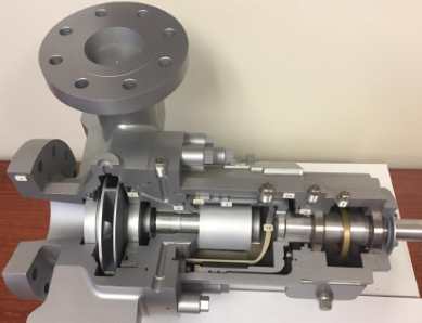
FIG. 1. Example of sealless MDP. Photo courtesy of Flowserve.
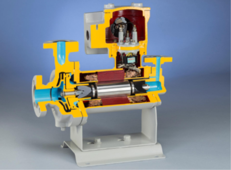
FIG. 2. Example of a sealless CMP. Photo courtesy of Teikoku, USA.
Three task force subgroups worked independently on one of the three sections. Afterwards, the entire task force reviewed each item to determine the final proposed changes to incorporate in the 3rd Ed.
Each task force subgroup carefully reviewed all bulleted paragraphs for making possible changes. A bullet (•) at the beginning of a clause or paragraph in an API document indicates either a decision by or further information from the purchaser is required. An example of this is a purchaser selecting “witnessing” a pump performance test (non-witness performance test is required for all API pumps; however, witnessing this test is an option that is beyond the default API requirements). There are slightly more than 100 bullet items in API 685. Specific bulleted items are addressed later in this article.
Task force formation and objectives. Numerous companies provided experts in their fields to produce the API 685 3rd Ed. document. Engineering contractors, end users and pump manufacturers comprised an international team to explore, discuss and debate a variety of topics. Eight end users, eight contractors/consultants and 21 vendors contributed to API 685 3rd Ed., with additional members from the SOME aiding when needed.
The following companies and several private consultants contributed to this work: Bechtel, KBR, Shell, Petrobras, Repsol, Total, bp Refining, Chevron, Phillips 66, Flowserve, Hermetic, ITT-Goulds, HMD-Kontro, Klaus Union GmbH, Teikoku, Nikkiso, Japan, Sulzer, Sundyne, Chemours, Mechanical Solutions Inc., Power Dyne Consultants and The Equity Engineering Group, Inc.
The API 685 task force was led by its Chairman, Jim Bryant, KBR (retired); Vice-Chair, Jeremy Cooper (Bechtel); and Secretary, Ian James (consultant).
The update process. API standards are on a 5-yr review cycle. Therefore, approximately 3 yr after a standard has been published, a task force is reformed to review the current standard and determine:
- If it requires updating to conform with current technology and market practices
- Whether it can be reaffirmed.
Presuming the decision is to revise the standard, the task force determines how best to accomplish the updating work, makes committee assignments and recommends proposed changes. All changes must be approved by the task force before they are included in the first draft of the revised standard.
One important step in the review process is for the task force to consider how any standard paragraphs within the API standards document (which applies to all equipment) pertain to specific paragraphs in the API 685 document. This provides a certain consistency among all rotating equipment. Decisions are made to either:
- Change the API 685 standard to agree with API SOME standard paragraphs
- Modify the standard paragraph to better suit the standard being reviewed
- Justify that the standard paragraph does not apply to the equipment for which the standard is intended and remove it.
The sequence process/timeline was provided earlier in this article. Some additional interesting details of this process follow:
- Global participation by members on the task force, as well as companies responding to the ballots, helped to ensure the specification applies worldwide
- The main roles of the task force chairman, vice chairman and secretary are to prepare proposed resolutions to each comment received. The proposed resolutions are presented to the task force to discuss and determine the wording that will become the presentation draft. The same process is used to produce the first ballot and any subsequent drafts.
- The criteria defined by API for passing a ballot and proceed to publishing is:
- Response rate must be > 50%
- Approval rate must be ≥ 66.7%
- Any negative ballot must be resolved.
The second and final ballot for API 685 3rd Ed. received a response rate of 76% based on 37 ballots, an approval rate of 100% and no negative ballots. All negative ballots must be resolved before the revised standard can be published.
The balloting process usually takes 1 mos–6 mos. The entire process usually takes between 2yr–4 yr, depending on the magnitude of the changes.
Significant additions and changes. The API 685 task force started the process of reviewing several items based on inputs from the SOME membership, industry leaders, updates from referenced specifications (such as the Hydraulic Institute) and task force members. Key additions or modifications recommended for API 685 3rd Ed. are as follows:
- Considerations for using API sealless pumps
- New informative annex addressing multi-stage overhung sealless pumps
- Inclusion of recommended practice API RP 691 “Risk Based Machinery Management”
- Material columns reduction/addition and improvements to material designations
- Updated annexes for material class selection guidelines and material columns
- Clearer definitions for secondary containment and secondary control, as well as methods to achieve these items
- Instrumentation and controls considerations
- Data sheets constructed to address all operating conditions
- Elimination of implied warranty
- Clarifications on baseplate types for MDPs and CMPs
- Pump selection criteria
- Clarification of several definitions, particularly “discharge pressure.”
Considerations for using API sealless pumps. One of the requests presented to the API 685 task force was to provide some inputs as to where and when sealless pumps are typically applied relative to specific applications and liquids often found in refineries and other hydrocarbon, petrochemical and gas plants. The decision was to include such information in the introduction section of the 3rd Ed. document. The listing is extensive and addresses what is generally categorized as “typically difficult services to seal” (i.e., with traditional API 610 pumps fitted with mechanical seals). These include the very light-end (low specific gravity) hydrocarbon liquids, acids such as sulfuric and hydrofluoric, and aromatics such as benzene. With stringent environmental requirements to minimize volatile organic compounds (VOC) emissions, sealless pumps become a candidate for consideration.
Each end user generally defines in their overlay specifications specific details as to when to use CMP and MDP products. Services with a high concentration of hydrogen sulfide (H2S) or those with amines or caustic solutions are candidates, as well. Often, solids size and concentration limits are also addressed with the sealless pump manufacturers based on their experiences and guidelines.
New annex: Multi-stage overhung sealless pumps. End users, contractors and pump manufacturers all asked: Why is API 685 limited to only single-stage overhung pumps (horizontal and vertical inline)? Since the 2nd Ed. of API 685 was issued back in 2011, the technology for sealless pumps has evolved to other configurations. The next question was: Why not include multi-stage overhung sealless pumps? To include these pumps in the body of the API 685 document would require extensive restructuring of the document (e.g., how API 610 addresses “between bearing” multi-stage pumps, and how two-stage overhung pumps require purchaser approval basis manufacturer’s proven experience).
The usage of multi-stage overhung sealless pumps at this stage is somewhat limited to certain manufacturers. As such, the task force submitted to the SOME a proposal to construct an informative (to inform, not mandate) annex that would highlight the various elements that an end user must consider when applying a multi-stage overhung sealless pump, and to include images of both multi-stage CMP and MDP configurations (FIG. 3). The SOME approved, so this annex has been included. It is considered the first step in a larger process, as this will most definitely be a subject for further discussion for the future 4th Ed. of API 685.
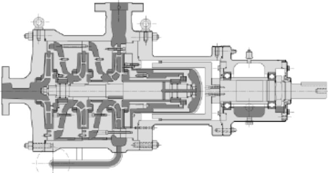
FIG. 3. Example of an overhung multi-stage MDP. Graphic courtesy of the Hydraulic Institute.
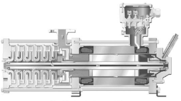
FIG. 4. Example of an overhung multi-stage CMP. Graphic courtesy of the Hydraulic Institute.
Inclusion of API RP 691: “Risk-Based Machinery Management.” API 685 3rd Ed. includes reference to API RP 691 by means of bulleted paragraphs, whereby the purchaser must advise the vendor when this recommended practice document is invoked. API RP 691 addresses high-risk machinery (i.e., compressors, pumps, engines, motors and gears, among others), suggested criteria as a function of fluid services limits and technical readiness levels (TRL), ranging from conceptual, prototype equipment to well-established, field-proven machinery.
When API RP 691 is invoked, the vendor is to advise whether equipment is not of the “field qualified” level, which translates to TRL 7 or 6. Level 7 is “field proven,” with equipment operating for more than 3 yr and that demonstrates low risk. Level 6 is “system installed,” whereby equipment has been operating successfully for less than 3 yr. The other TRLs describe the “state of development” (or stages) for a product. Level 1 is just a concept; Level 2 is proof of concept; and Levels 3–5 cover prototype stages. Any of these lower levels need careful review between the purchaser and vendor in evaluating the risk for the product and the end user’s system. Note: all future updates of any API standard will include API RP 691.
Materials. Changes were made to API 685 3rd Ed. “Annexes for Materials Class Selection Guidance” (Annex G) and “Materials and Material Specifications for Pump Parts” (Annex H) in part to be consistent with the changes implemented in API 610 12th Ed. Consideration was given to what additional materials may be needed for sealless pumps due to their different configuration with containment shells, secondary control and secondary containment relative to the types of service fluids they handle. The key changes included the following:
- The deletion of cast iron material columns I-1 and I-2 since API pump manufacturers generally no longer pour cast iron casings, and API users generally want a repairable material (starting with carbon steel) for pressure boundary parts.
- The deletion of columns S-1 and S-3, as there is little usage of cast iron and Ni-resist internals. Also, like the reasoning to eliminate I-1 and I-2 material columns, repair welding these materials is difficult. The new starting point is S-4.
- Annex G upgraded recommended materials for caustic (sodium hydroxide) with concentrations of ≤ 20%, and temperatures < 100°C (210°F) have been upgraded from S-1 to S-4 or A-8 since S-1 materials have been removed from API 685 3rd as addressed above.
- The addition of material codes for the following: Alloy 20 for the U.S. (ASTM), unified numbering system (UNS), European (EN) and Japanese (JIS); Japanese codes for Alloy B and Alloy C; and the new Ni-Cu Alloy 400.
- For S-6 materials, changing 4140 shaft material to 12% chrome to ensure thermal growth compatibility between the impeller and the shaft, and to be consistent with API 610 12th
- The removal of CA15 for impellers. CA6NM was already required for pump casings in API 610 11th and is now consistent with the 12th Ed, and is recommended for improved castability, weldability and resistance to in-service stress cracking.
- For C-6 materials, under auxiliary connections, 316L piping and fittings are to be used up to 260°C (500°F), and Inconel 625 for temperatures above 260°C (500°F).
- For consistency with API 610 12th, when reduced hardness materials are specified by the customer, the requirement applies to both the primary and secondary casings, and to NACE MR0103 (which applies to refineries, LNG and chemical plants), unless the customer specifies MR0175 (which applies to oil and gas production units and natural gas sweetening plants).
- Prohibition of cadmium-plated piping bolting due to the carcinogenic nature of cadmium.
- Regarding magnetic coupling materials (addressed in Annex D) for MDPs, increased values for remanence of maximum magnetic flux density, coercivity (demagnetizing force) and maximum BH product (overall magnetic strength). Sm1Co5 and Alnico 5 have been removed since they are superseded by Sm2Co17 and Alnico8 materials.
Secondary controls and containment and instrumentation and controls. Details of secondary controls and containment, along with instrumentation and controls will be discussed in Part 3.
Elimination of implied warranty. As done with API 610 12th Ed., API 685 3rd Ed. was updated to remove wording about a 20-yr minimum service life, excluding normal wear parts, and a stipulation of an uninterrupted operation period of 3 yr (without shutting down equipment for maintenance or inspection). The wording regarding service life was replaced by wording that states that the purchaser should specify the period of uninterrupted continuous operation. Most manufacturers’ installation, operation and maintenance (IOM) manuals address items such as frequency for changing oil and identifying parts that are expected to be replaced due to normal wear over time. The IOM manuals also typically have recommendations as to which parts the end user should stock as spares. Table L1 in Annex L of API 685 3rd Ed. provides guidance on which parts and what quantity are recommended to be provided as spares.
Baseplates. There are two interesting changes that were made to API 685 2nd Ed. to represent the current industry practices regarding CMP and MDP baseplates. These are: eliminating Annex M and improving the descriptions of baseplate types used for MDP.
Annex M in API 685 2nd Ed. (“Standard Baseplates”) has been eliminated in API 685 3rd Ed. Annex M was normative and provided 21 pre-engineered baseplate sizes, along with their anchor bolt locations (identical to API 610 11th Ed.). The primary reasons behind removing Annex M were:
- There is no coupling between the canned motor and pump. CMPs do not require a typical API 610-style baseplate. The unit footprint is significantly smaller than that used for conventional 610 and 685 MDP packages, which require room to accommodate an external motor and coupling. Conversely, CMP installations are configured such that the pumps are often free to move with the piping system, especially for small sizes.
- Typically, MDP packages utilize smaller ranges of driver power. The packages use smaller baseplates because there are usually not auxiliary sealing systems (e.g., plan 52, 53 or gas panels) which generally require the larger baseplates used for API 610 pumps.
- Engineering contractors are now satisfied with vendors issuing general arrangement drawings in a timely matter due to improved electronic systems to generate them.
Descriptions of the three basic types of baseplates for MDP were improved to depict the baseplate types (identical to API 610 12th Ed.) more accurately. Drain rim and drain pan are removed and replaced with:
- A baseplate with a flat deck type and a sloped gutter drain
- A baseplate with a sloped deck plate mounted between the side rails and extending beneath the pump and driver
- A baseplate with a sloped deck plate mounted between the side rails and extending only under the pump and coupling
It remains the responsibility of the end user to select one of the three baseplate configurations.
Pump selection criteria. The one significant change impacting pump selections is for the head curve to be continuously rising to shutoff (zero flow). In 685 2nd Ed., it was preferred. Now, however, both API 685 3rd Ed. and API 610 12th Ed. require a rising head curve: only when specified by the end user and always when pumps run in parallel (to prevent one pump driving the other to shut-off flow).
This was changed because it is characteristic of low-specific speed pumps for their head curves to sometimes droop at shutoff. It should be noted that irrespective of the change in both API standards, many end user’s overlay specifications still require a head curve that continuously rises to shutoff.
“End of curve” is now defined as 120% of best efficiency point (BEP). However, for low-specific speed pumps, the end of curve may be only 105% to 110% of BEP because the head curve drops off quickly for these types of pumps. Also, it is preferred that the pump BEP flow rate is between the rated point and the normal flow point to maximize pump efficiency between the two main operating points on the pump performance curve. API 685 2nd Ed. did not mention normal point, but now it is addressed within the specification and on the data sheets. These changes are consistent with API 610 12th Ed.
Wording for new positive suction head available (NPSH) and NPSH3 requirements have been modified to be consistent with API 610 12th Ed. Most important is the reference point for defining NPSHA. This can be either the pump centerline, which is the typical reference for defining NPSH3, or top of foundation in which case a minor adjustment in the values must be made for the slight difference in elevation. The key is for the pump vendor and purchaser to agree to the NPSH margin to prevent any flashing of the liquid. The Hydraulic Institute’s Standard 9.6 is a good reference to use as a guideline to determine appropriate NPSH margin for different types of pumps and services.
A new item pertaining to MDP states that foot-mounted pumps with a nominal impeller diameter up to 200 mm (8 in) may be used at temperatures greater than 175°C (350°F). API 685 2nd Ed. had previously required centerline supported pump casings for all horizontal MDPs, whereas API 685 3rd Ed. recognizes that centerline supported casings may not be required for the smaller size MDPs at higher temperatures.
Definitions. One key definition change which was done to align with API 610 12th Ed. is maximum discharge pressure. API 685 3rd Ed. now states that the relative density (specific gravity) for the respective operating cases (as indicated on the data sheets) is to be used to determine the maximum discharge pressure. Of interest, is that API 610 11th Ed. based this pressure on the normal specific gravity. It was realized by the 12th Ed. task force that the change was required to address the most severe case when determining the maximum allowable working pressure (MAWP). In addition to the conditions of service, any operation with temporary liquid of higher density (e.g., pumping cleaning liquids) must be included in establishing the maximum discharge pressure.
New wording added to clearly define the pressure boundary components for both sealless pump designs. The pressure boundary components are defined as:
- Casing, casing plate and the containment shell for MDPs
- Casing, casing plate and the stator liner for CMPs.
Takeaways. Part 1 of this article on API 685 has highlighted most of the significant changes reflected in the July 2022 published 3rd Ed. of the standard. Part 2 will provide insights into the various other points of discussion the API 685 task force addressed, as well as the rationale used to evaluate the changes and additions that were incorporated. Part 3 addresses secondary control and secondary containment, along with associated instrumentation requirements.
Where do we go from here? Do we keep API 685 as a standalone document or perhaps make it part of API 610? Do we expand API 685 to include overhung multi-stage sealless pump designs within the main body of the future standard? What new technology must be explored and applied to API 685?
The authors welcome all comments and suggestions for topics—within and beyond what has been addressed in this article—for additional consideration.
NOTE
Parts 2 and 3 of this article will be posted to the Hydrocarbon Processing site soon. The contents of this article originally appeared in the proceedings of the Turbomachinery and Pump Symposium held in Houston, Texas (U.S.) in September 2022.
REFERENCES
1 API Standard 685 3rd Ed., “Sealless Centrifugal Pumps for Petroleum, Petrochemical, and Gas Industry Process Service,” API, July 2022.
2 API Standard 685 2nd Ed., “Sealless Centrifugal Pumps for Petroleum, Petrochemical, and Gas Industry Process Service,” API, February 2011.
3 API Standard 610 12th Ed., “Centrifugal Pumps for Petroleum, Petrochemical and Natural Gas Industries,” API, January 2021
4 ANSI/API Standard 610 11th Ed., “Centrifugal Pumps for Petroleum, Petrochemical and Natural Gas Industries,” ANSI/API, (ISO 13709:2009) (Identical), September 2010.
5 Hydraulic Institute, ANSI/HI 5.1-5.6-2016, “Sealless Rotodynamic Pumps for Nomenclature, Definitions, Design, Application, Operation and Test,” 2016.
6 Hydraulic Institute, ANSI/HI 9.6.1-2007, “Rotodynamic Pumps—Guideline for NPSH Margin
Pumps and Systems,” October 26, 2016, Canned Motor Pumps, Magnetic Couplings and Sealless Rotodynamic Pumps.
7 Karassik, I. J., J. P. Messina, P. Cooper and C. C. Heald, Pump Handbook, McGraw-Hill, New York, New York, 2008
8 Korkowski, F., J. Cooper, T. Hess and M. V. D. Heuvel, “Highlights of API 685 Third Edition,” 51st Turbomachinery and 38th Pump Symposia, Houston, Texas, September 2022.
9 Korkowski, F., R. Jones and J. Cooper, “Preview of API 610 Twelfth Edition,” 43rd Turbomachinery and 30th Pump Users Symposia, Houston, Texas, September 2014
10 Korkowski, F., R. Jones and J. Cooper, “Highlights of Draft API 610 Twelfth Edition,” 45th Turbomachinery and 32nd Pump Users Symposia, Houston, Texas, September 2016.
11 Bryant, J. and S. Bennett, “API 685 Tutorial,” 12th International Pump Users Symposium, Houston, Texas, 2003.
ACKNOWLEDGEMENTS
To all the engineers and their respective companies who participate and serve on the API 685 task force, thank you for your inputs, research and discussions which molded the framework to propose the 3rd Ed. update. Appreciation is extended to the API for their continuous support and encouragement to produce updates to this global pump standard. The authors also want to thank the companies of the engineers who worked to produce the new Annex on multi-stage overhung sealless pumps. A special thank you to API 685 original task force Chairman Jim Bryant (recently retired from KBR), who guided the task force members in documenting all the final edits required for updating to the 3rd Ed. Lastly, appreciation to TriComB2B company and Melissa Lorenz for her work on this paper.
THE AUTHORS
Frank Korkowski (korkowskifrancis@gmail.com) is the Director of Engineered Training at Applied K3nowledge Consulting. He is a consultant recently retired from Flowserve and previously was the Marketing Manager for the API 1- and 2-stage process pumps. He spent 45 yr in various pump roles with Ingersoll Rand, Ingersoll-Dresser Pumps and Flowserve. Korkowski earned a BS degree in industrial engineering from the New Jersey Institute of Technology, with post-graduate studies in mechanical engineering and business administration at Lafayette College and Fairleigh Dickinson University. For the last 25 yr, he has served on API task forces API 610, API 685, API RP-691, and currently on API 682 and API 674.
Tom Hess (thess@e2g.com) is the Principal Rotating Engineer for The Equity Engineering Group, Inc. Prior to joining Equity, Hess worked as a Rotating Reliability Engineer in an oil refinery. He has been fascinated with sealless pumps for nearly 30 yr. He earned his BSME degree from Villanova University, is a member of ASME and is a registered professional engineer in the Commonwealth of Pennsylvania. Hess is a member of the API 685, 610, 682 and 613 Task Forces.
Jeremy Cooper (tjcooper@bechtel.com) is a Principal Rotating Equipment Specialist for Bechtel Inc. in Houston, Texas (U.S.). Since 2001, he has worked as a Project Manager and Project Engineer with suppliers such as Flowserve and IFS. Prior to joining Bechtel, he was a Rotating Equipment Engineer at Fluor. Cooper currently serves as the Chairman of the API SOME, is the task force chairman of API 610 and API 685 and participates in several other task forces. He has worked startup and commissioning assignments in both international and domestic projects and is currently the Functional Lead for Rotating Equipment at Bechtel.
Martein van den Heuvel (Marteinvanden.Heuvel@bp.com) is a Senior Rotating Systems Engineer working for the central innovation and engineering team of bp. This year, he celebrated 30 yr of rotating equipment related experience in various operational, maintenance and engineering roles in the chemical and oil and gas industry. Heuvel received a BS degree in Mechanical Engineering from the Technische Hogeschool Rotterdam and a MS degree (honors) in maintenance management from the Caledonian University in Glasgow. He is a member of the API 685 taskforce.


Comments