
Digital Exclusive: Water injection pump mechanical seals failure after pump shutdown
W. KHALAF ALLAH and A. AL-DHAFIRI, Saudi Aramco, Dhahran, Saudi Arabia
A water injection pump of a between-bearing design experienced excessive and visible mechanical seal leakage from both the drive end (DE) and the non-drive end (NDE) shortly after pump shutdown. The pump is equipped with dual pressurized seals that comply with the American Petroleum Institute (API) Seal Plan 54. The barrier liquid of Plan 54 is International Standards Organization (ISO) viscosity grade (VG) 32 oil. TABLE 1 shows basic pump and process information.
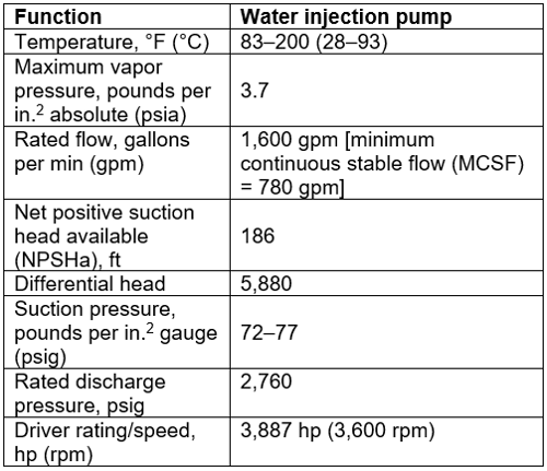
TABLE 1. Basic pump and process information
This article shows how the isolation of pump suction piping can lead to pump over-pressurization, causing mechanical seals catastrophic failure.
Pump, seal and system design. FIG. 1 shows a between-bearing pump of the double-casing design, as per API 610 BB5 configuration. The pump is designed for a maximum allowable working pressure (MAWP) of 3,700 psig. The mechanical seal gland is designed to handle the same pressure as mandated by API 682. However, mechanical seal faces cannot handle such high pressure dynamically or statically because the seal faces will break far below the pump’s MAWP. This is one of the reasons it is essential to ensure the pump will not be exposed to such high pressure when in standby mode.
For the subject pump system, the pump discharge piping class rating is 2,500, and the suction piping class rating is 150. As both suction piping and discharge piping are equipped with motor operated valves (MOVs), the pump system is designed with a dumping ZV (the valve used to bring the pump pressure to zero) on the pump suction piping, as can be seen in FIG. 1. The dumping ZV is interlocked with a suction piping MOV to ensure it opens when the suction piping MOV closes to prevent over-pressurization. Due to the absence of a suction tank, the dumping ZV directs the water to an evaporation pound.
Although the process liquid is not considered toxic or hazardous, it has an extremely high salt content, achieving a total dissolved salt of 67,000 parts per million (ppm). This means the process liquid is unsuitable for use in lubricating mechanical seal faces, as the salt will be deposited at the seal faces atmospheric side leading to frequent seal failures. Therefore, the pump was equipped with dual pressurized seals that utilize ISO VG 32 oil as barrier liquid.
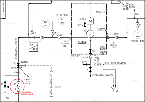
FIG. 1. Pump system piping and instrumentation diagram (P&ID).
Findings and analysis. To identify the root causes of such failure, the team examined the distributed control system (DCS) to search for any abnormal behavior. Although the pump did not have individual suction or discharge pressure transmitters, it did have a pressure transmitter in Plan 54 to monitor seal barrier liquid pressure. FIG. 2 shows a snapshoot of Plan 54 that indicates abnormal behavior as the pressure reached 400 psig after pump shutdown, which far exceeds the Plan 54 normal operating pressure of 170 psig.
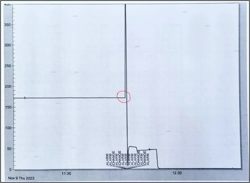
FIG. 2. Seal oil pressure spike after pump shutdown.
FIG. 2 clearly indicates that Plan 54 was over-pressurized: this was believed to be caused by high pressure in the system after pump shutdown. This is supported by the large water quantities seen in the Plan 54 barrier oil liquid tank. Consequently, the seal faces broke, leading to excessive leakage to the atmosphere that caused the pressure to drop to 0 psig.
Normally, the pump should stay at a suction pressure of 75 psig when the pump shuts down. However, in this case, the pressure far exceeded the suction pressure. In fact, the 400 psig represents the pressure transmitter reading limit, which means that the actual pressure was probably higher.
Another source that helped the team to analyze the failure was an investigation of the failed mechanical seals. The images of the failed seals shown in FIGS. 3 and 4 clearly indicate the seal faces were broken to pieces and had severe markings on the seal gland metallic surface.

FIG. 3. Broken inboard primary and mating rings.

FIG. 4. Mechanical seal gland plate damaged by cracked seal faces.
The primary assumed scenario for this failure is that the seal was operating healthy with acceptable leakage rate (no more than 2 drops per minute) while the pump was running. After the pump was shut down, closing the suction isolation valve led to over-pressurization in the pump suction piping and seal chamber due to the recycle valve closing and possible malfunction or delayed response of dumping ZV. Alternatively, the dumping ZV may have functioned properly, but the manual valve downstream of it may have been in the closed position by mistake.
Although the discharge valve was closed and the discharge piping is equipped with a check valve, this will never prevent over-pressurization as the discharge valve has very high differential pressure across it. In fact, even if the valve has a tight shutoff design, it will still have some allowable leakage as per valve standards—this can cause pump over-pressurization in a short duration as the pump liquid is not compressible and all escape paths (e.g., suction valve, recycle valve, dumping ZV) are closed. This is evident in the seal oil pressure spike shown in FIG. 2, which seems to exceed the seal pressure transmitter range.
This spike completely damaged the seal faces and cracked them into several pieces. Finally, the pump was most likely rotated for a very short duration after it was shutdown, which caused the cracked seal faces to act as a grinder and damage the seal gland plate and other internal components, as shown in FIGS. 3 and 4.
Recommendations. The following recommendations are essential to conduct proper future failure investigations and to correct system issues to avoid future seal failures:
- Ensure the inter-locks of the suction MOV and the dumping ZV activate at the same time to prevent potential over-pressurization. The suction valve should close before the dumping ZV opens.
- Add a suction pressure transmitter with a high-pressure alarm.
- Car seal open all manual valves in the dumping ZV line.
- Operators should monitor pump startup and shutdown procedures and ensure dumping line proper line-up to avoid future failures.
ABOUT THE AUTHORS
Wesam Khalaf Allah is a Lead Engineer within Saudi Aramco’s ECSD with 14 yrs of experience in pumps and mechanical seals. He holds an MS degree in mechanical engineering from Texas A&M University. The author can be reached at wesam.khalafallah@aramco.com.
Amer Al-Dhafiri is a Senior Engineering Consultant within Saudi Aramco’s Equipment Consutling Services Department (ECSD) with 30 yrs of experience in pumps and mechanical seals. The author can be reached at Amer.dhafiri@aramco.com.

Comments